准备工作
- 实验会创建一个 Google Cloud 项目和一些资源,供您使用限定的一段时间
- 实验有时间限制,并且没有暂停功能。如果您中途结束实验,则必须重新开始。
- 在屏幕左上角,点击开始实验即可开始
Finish setting up network infrastructure
/ 50
Configure the internal load balancer
/ 50
Finish setting up network infrastructure
/ 50
Configure the internal load balancer
/ 50
Google Cloud load balancers offer traffic management capabilities that vary by load balancer.
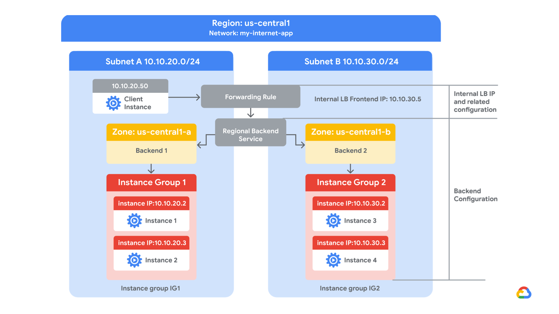
In this lab, you create a regional internal Application Load Balancer with two backends. Each backend will be an instance group. You will configure the load balancer to create a blue-green deployment.
The blue deployment refers to the current version of your application, and the green deployment refers to a new application version. You configure the load balancer to send 70% of the traffic to the blue deployment and 30% to the green deployment. When you’re finished, the environment will look like this:
In this lab, you perform the following tasks:
For each lab, you get a new Google Cloud project and set of resources for a fixed time at no cost.
Click the Start Lab button. If you need to pay for the lab, a pop-up opens for you to select your payment method. On the left is the Lab Details panel with the following:
Click Open Google Cloud console (or right-click and select Open Link in Incognito Window if you are running the Chrome browser).
The lab spins up resources, and then opens another tab that shows the Sign in page.
Tip: Arrange the tabs in separate windows, side-by-side.
If necessary, copy the Username below and paste it into the Sign in dialog.
You can also find the Username in the Lab Details panel.
Click Next.
Copy the Password below and paste it into the Welcome dialog.
You can also find the Password in the Lab Details panel.
Click Next.
Click through the subsequent pages:
After a few moments, the Google Cloud console opens in this tab.
In this task, you explore the pre-configured Google Cloud infrastructure, including the network, firewall rules, and instance groups, that the load balancer will utilize. You then create a test VM and verify the backend instances.
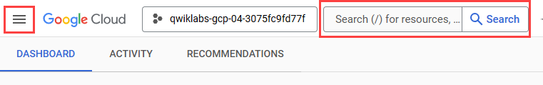
In the Google Cloud console, in the Navigation menu (
Each Google Cloud project starts with the default network. In addition, the my-internal-app network was created for you as part of your network diagram.
Note the my-internal-app network with its subnets: subnet-a and subnet-b. Both subnets are in the
Managed instance groups in subnet-a and subnet-b were also created for you.
(Optional) Click subnet-a and observe its configuration.
(Optional) Click subnet-b and observe its configuration.
In the Navigation menu (
Note the following firewall rules that were created for you:
| Firewall rule | Purpose |
|---|---|
| app-allow-icmp | Allows ICMP communication |
| app-allow-ssh-rdp | Allows SSH and RDP over TCP ports 22 and 3389 |
| fw-allow-health-checks | Allow health checks over TCP port 80 |
| fw-allow-lb-access | Allow traffic in the 10.10.0.0/16 subnet |
(Optional) View the contents of each firewall rule.
In the Google Cloud console, in the Navigation menu (
The instance groups were created for you. Next, you will observe the configuration details.
On the Navigation menu, click Compute Engine > VM instances.
Note the two VM instances that start with instance-group-1 and instance-group-2.
Click instance-group-1.
Scroll to Network interfaces.
Note that the instance group is in subnet-a, and its internal IP address is 10.10.20.2.
Return to the VM instances page, and repeat steps 2 and 3 for instance-group-2.
Note that this instance group is in subnet-b, and its internal IP address is 10.10.30.2.
You create a VM called utility-vm in subnet-a of the my-internal-app network and use it to test the load balancer.
Return to the VM instances page, and click Create instance.
Specify the following, and leave the remaining settings as their defaults:
| Property | Value (type value or select option as specified) |
|---|---|
| Name | utility-vm |
| Region | |
| Zone | |
| Series | E2 |
| Machine type | e2-medium (2vCPU, 4 GB memory) |
Click OS and storage.
Click Change to begin configuring your boot disk and select the following values:
Debian
Debian GNU/Linux 12 (bookworm) x86/64, amd64
Click Networking.
For Network interfaces, click default.
Set the network interface properties and values as shown in the following table, and leave the remaining properties as their default values:
| Property | Value (type value or select option as specified) |
|---|---|
| Network | my-internal-app |
| Subnetwork | subnet-a |
| Primary internal IPv4 address | Ephemeral (Custom) |
| Custom ephemeral IP address | 10.10.20.50 |
| External IPv4 address | None |
Click Done.
Click Create.
Wait for the new VM to be created.
For utility-vm, click SSH to launch a terminal and connect.
If you see the Allow SSH-in-browser to connect to VMs pop-up, click Authorize.
To verify the welcome page for instance-group-1-xxxx, run the following command:
The output is shown below. Note that the server location is set to
The output is shown below. Note that the server location is set to
Click Check my progress to verify the objective.
In this task, you configure a regional internal Application Load Balancer to balance traffic between the two backends (instance-group-1 in
In the Google Cloud console, in the Navigation menu (
Click Create load balancer.
Under Application Load Balancer (HTTP/HTTPS), click next.
For Public facing or internal, select internal and click next.
This selection creates a regional internal Application Load Balancer. This choice requires the backends to be in a single region
For Cross-region or single region deployment, select Best for regional workloads and click next.
Click Configure.
For Name, type my-ilb
For Region, select
For Network, select my-internal-app.
The proxy servers that implement the regional internal Application Load Balancer require IP addresses. These IP addresses are allocated automatically from a subnet that you specify.
Under Proxy-only subnet required, click Reserve subnet.
For Name, type my-proxy-subnet
For IP address range, type 10.10.40.0/24
Click Add.
Wait for the proxy-only subnet to be created. When that is successful, the console displays the name of the proxy-only subnet followed by the IP address range that you specified.
This backend service refers to the present ("blue") version of your application.
Click Backend configuration.
For Backend configuration, for Create or select backend service, select Create a backend service.
For Name, type blue-service.
In Backends, specify the following, and leave the remaining settings as their defaults:
| Property | Value (type value or select option as specified) |
|---|---|
| Instance group | instance-group-1 |
| Port numbers | 80 |
Click Done.
For Health check, select Create a health check.
Specify the following, and leave the remaining settings as their defaults:
| Property | Value (select option as specified) |
|---|---|
| Name | blue-health-check |
| Protocol | TCP |
| Port | 80 |
| Check interval | 10 seconds |
| Timeout | 5 seconds |
| Healthy threshold | 2 |
| Unhealthy threshold | 3 |
Click Save.
Click Create.
Verify that there is a blue check mark next to Backend configuration in the Google Cloud console. If there isn't, double-check that you have completed all the steps above.
This backend service refers to the new ("green") version of your application.
For Backend configuration, for Create or select backend service, select Create a backend service.
For Name, type green-service.
In Backends, specify the following, and leave the remaining settings as their defaults:
| Property | Value (type value or select option as specified) |
|---|---|
| Instance group | instance-group-2 |
| Port numbers | 80 |
Click Done.
For Health check, select Create a health check.
Specify the following, and leave the remaining settings as their defaults:
| Property | Value (select option as specified) |
|---|---|
| Name | green-health-check |
| Protocol | TCP |
| Port | 80 |
| Check interval | 10 seconds |
| Timeout | 5 seconds |
| Healthy threshold | 2 |
| Unhealthy threshold | 3 |
Click Save.
Click Create.
Under Backend services, you should now see two entries: one for the blue-service and another for the green-service. If you do not see the green-service, you will need to re-do the task Configure the green-service backend.
Create a routing rule that routes 70% of traffic to the blue-service and 30% of traffic to the green service.
Click Routing rules.
In the Routing rules panel, for Mode, select Advanded host and path rule.
Click Add host and path rule.
For Hosts, type *. The * (asterisk) matches all hosts.
Traffic management is configured using YAML format. Examine the following YAML code, and then copy and paste it into line 1 of the multi-line field Path matcher (matches, actions, and services).
When traffic does not match any of the other routing rules, the load balancer uses the default routing rule. Even though the rule you configured is designed to match all traffic, the default routing rule is required. You will configure the default routing rule to use the blue-service backend.
Click (Default) Route traffic to backend "" for any unmatched hosts.
In the Edit host and path rule panel, for Service, select blue-service, and then click Done.
The frontend forwards traffic to the backends.
Click Frontend configuration.
Specify the following, and leave the remaining settings as their defaults:
| Property | Value (type value or select option as specified) |
|---|---|
| Subnetwork | subnet-b |
| IP address | Ephemeral (Custom) |
| Custom ephemeral IP address | 10.10.30.5 |
Click Done.
(Optional) Click Review and finalize. Review the Backend and Frontend.
Click Create.
Wait for the load balancer to be created before starting the next task.
Click Check my progress to verify the objective.
In this task, you verify that the my-ilb IP address forwards most of the traffic to the blue-service running on instance-group-1 in
In the Navigation menu, click Compute Engine > VM instances.
For utility-vm, click SSH to launch a terminal and connect.
To verify that the load balancer forwards traffic, run the following command:
The output should look like this:
Most responses should come from instance-group-1 in
In this lab, you created two managed instance groups in the
When you have completed your lab, click End Lab. Google Skills removes the resources you’ve used and cleans the account for you.
You will be given an opportunity to rate the lab experience. Select the applicable number of stars, type a comment, and then click Submit.
The number of stars indicates the following:
You can close the dialog box if you don't want to provide feedback.
For feedback, suggestions, or corrections, please use the Support tab.
Copyright 2026 Google LLC All rights reserved. Google and the Google logo are trademarks of Google LLC. All other company and product names may be trademarks of the respective companies with which they are associated.


此内容目前不可用
一旦可用,我们会通过电子邮件告知您
太好了!
一旦可用,我们会通过电子邮件告知您

一次一个实验
确认结束所有现有实验并开始此实验
完成此快速步骤即可开始实验。